Project details
Skill
Cost
Estimated Time
We may be compensated if you purchase through links on our website. Our team is committed to delivering honest, objective, and independent reviews on home products and services.
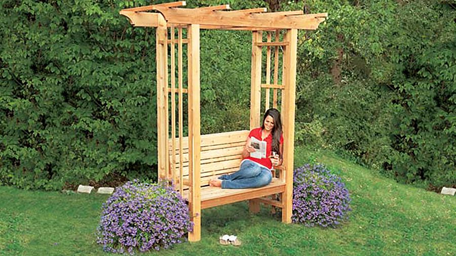
You could plop a couple of deck chairs in your backyard for an impromptu sitting area. But a hand-built cedar bench, framed by an arbor, gives you a permanent place to kick back as the weather warms.
Our design incorporates classic touches, though you can make a more simple version as well. Follow along as This Old House senior technical editor Mark Powers puts it all together.
Planning Your Arbor Bench
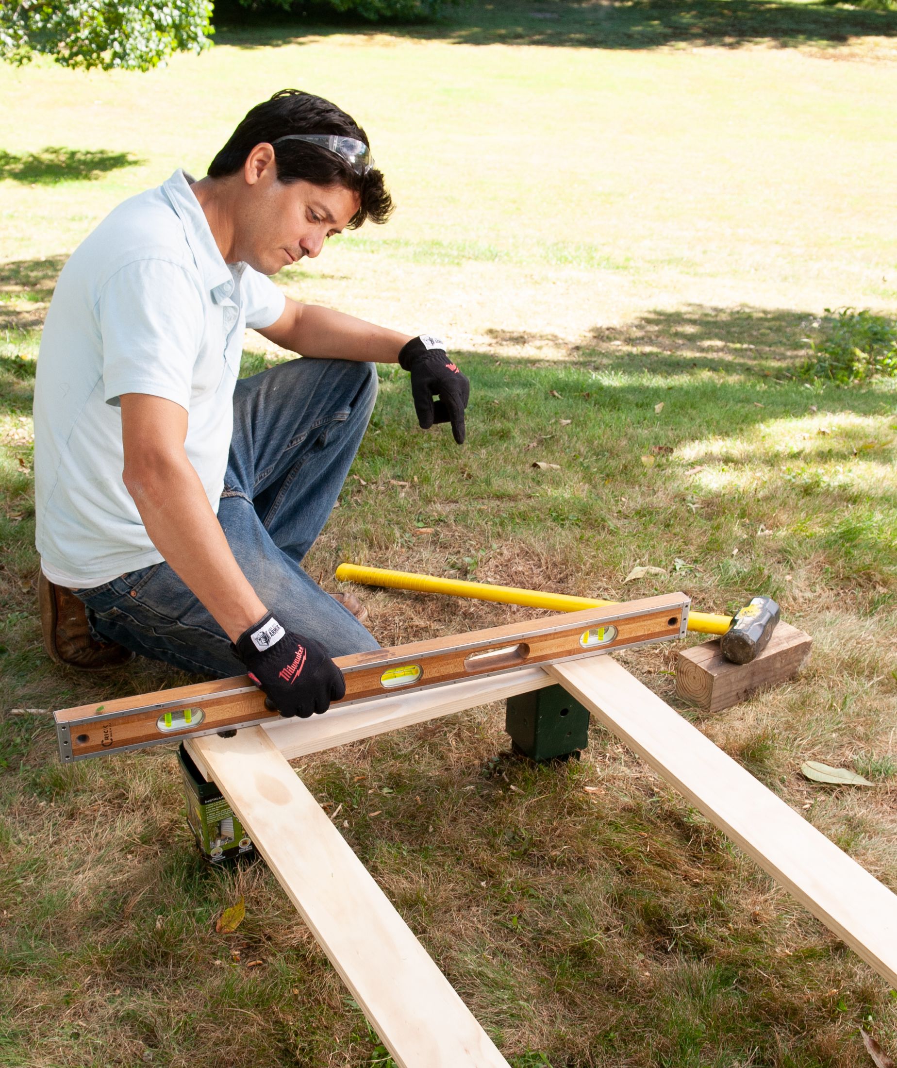
Before diving into construction, it’s essential to plan your project carefully. Select a spot in your yard that offers the best views or complements existing landscaping. Build on level ground that can support the structure’s weight.
Materials and Tools
To build an arbor bench, you’ll need:
- Western red cedar lumber (2x4s, 2x6s, 1x4s, 1x2s)
- Post anchors
- Construction adhesive
- Exterior wood screws
- Miter saw
- Jigsaw
- Drill/driver
- Level
- Measuring tape
- Pencil
- Safety equipment (goggles, gloves, ear protection)
How to Build an Arbor Bench: Step-by-Step
This cedar structure not only provides a cozy spot to relax but also serves as an eye-catching focal point in your yard. With some basic carpentry skills and the right materials, you can create this stunning arbor bench over the course of a few days.
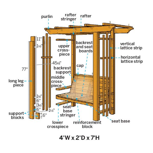
Cut List
- 2×4 seat-base stringers: 3 @ 18 inches
- 2×4 reinforcement block for seat base’s center stringer: 1 @ 14 inches from square edge to long point, one end mitered at 30 degrees
- 2×4 backrest supports: 3 @ 22 inches from long point to short point, with parallel 30-degree cuts off each end
- 1×4 seat boards: 3 @ 48 inches
- 1×2 seat boards: 3 @ 48 inches
- 1×4 backrest boards: 4 @ 40 ¾ inches
- 1×2 backrest boards: 3 @ 40 ¾ inches
- 1×4 backrest cap: 1 @ 40 ¾ inches
- 1×2 lattice: 4 @ 70 ½ inches
- 1×2 lattice: 2 @ 75 ½ inches
- 1×2 lattice: 2 @ 17 inches
- 2×6 rafters: 2 @ 72 inches
- 2×6 rafter stringers: 3 @ 21 inches
- 2×2 purlins: 5 @ 36 inches
Step 1: Make Pilot Holes for the Post Anchors
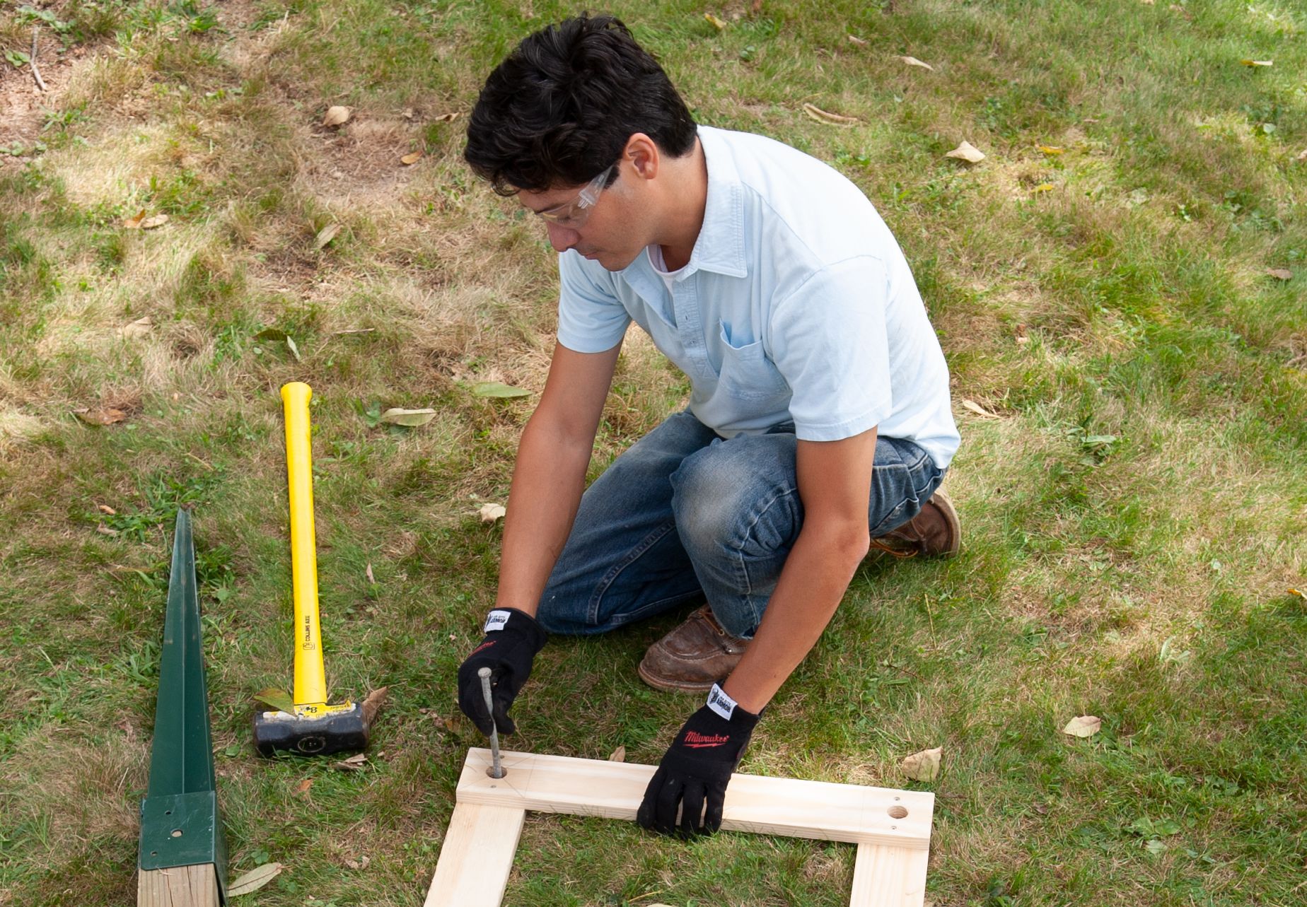
Cut and screw together four scrap 1x4s to make a rectangular template sized to the bench’s footprint, per the cut list. Drill a centered 1-inch hole in each corner. Lay the template on the ground and push a large nail or stake through each hole.
Remove the template and set it aside.
Step 2: Set the Post Anchors
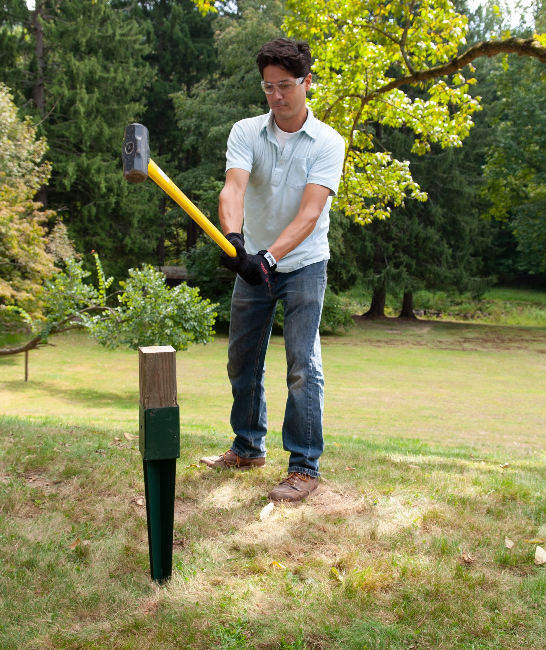
Place the tips of the post anchors in the pilot holes you made in Step 1. Make sure the anchors are parallel to one another and square with the bench’s footprint.
Place a scrap block of wood into one anchor and strike it with a sledgehammer until the anchor’s base touches the ground. Repeat for the remaining anchors.
Step 3: Level and Square the Post Anchors
Place the template on top of the anchors and check it for level, making adjustments as necessary. Again, make sure the anchors are parallel to one another and square to the bench’s footprint.
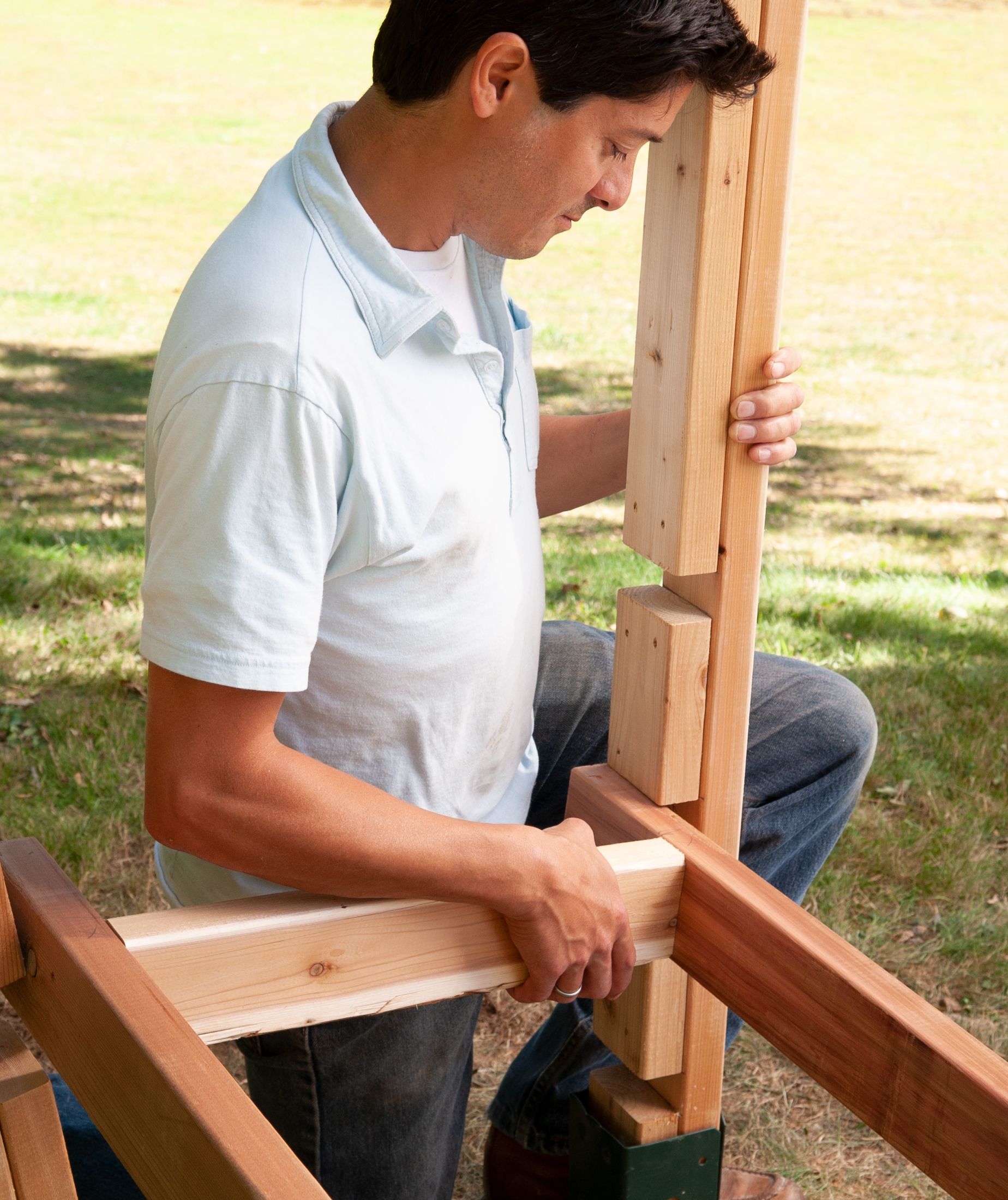
Step 4: Dry-fit the Pieces
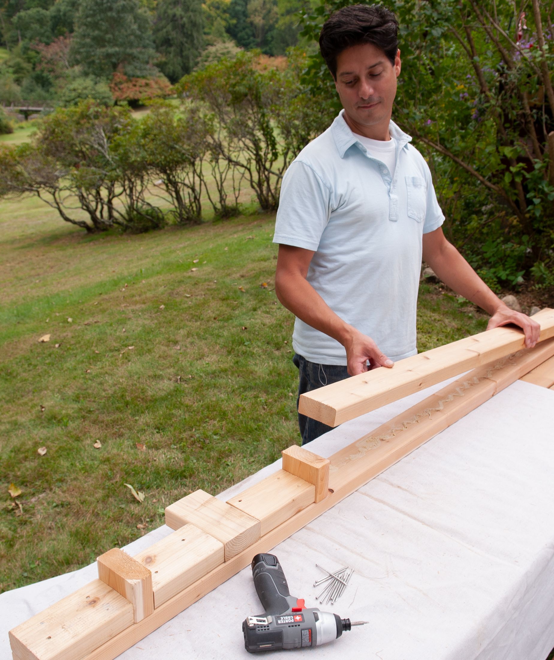
Refer to the diagram. Each leg is made from one long 2×4 built up with 2×4 support blocks separated by gaps where the crosspieces, bench, and rafter assembly will be attached.
Cut the pieces to size per the cut list, then lay out a set of leg pieces on a flat surface, using scrap blocks of 2×4 as spacers between the support blocks.
Step 5: Assemble the Legs
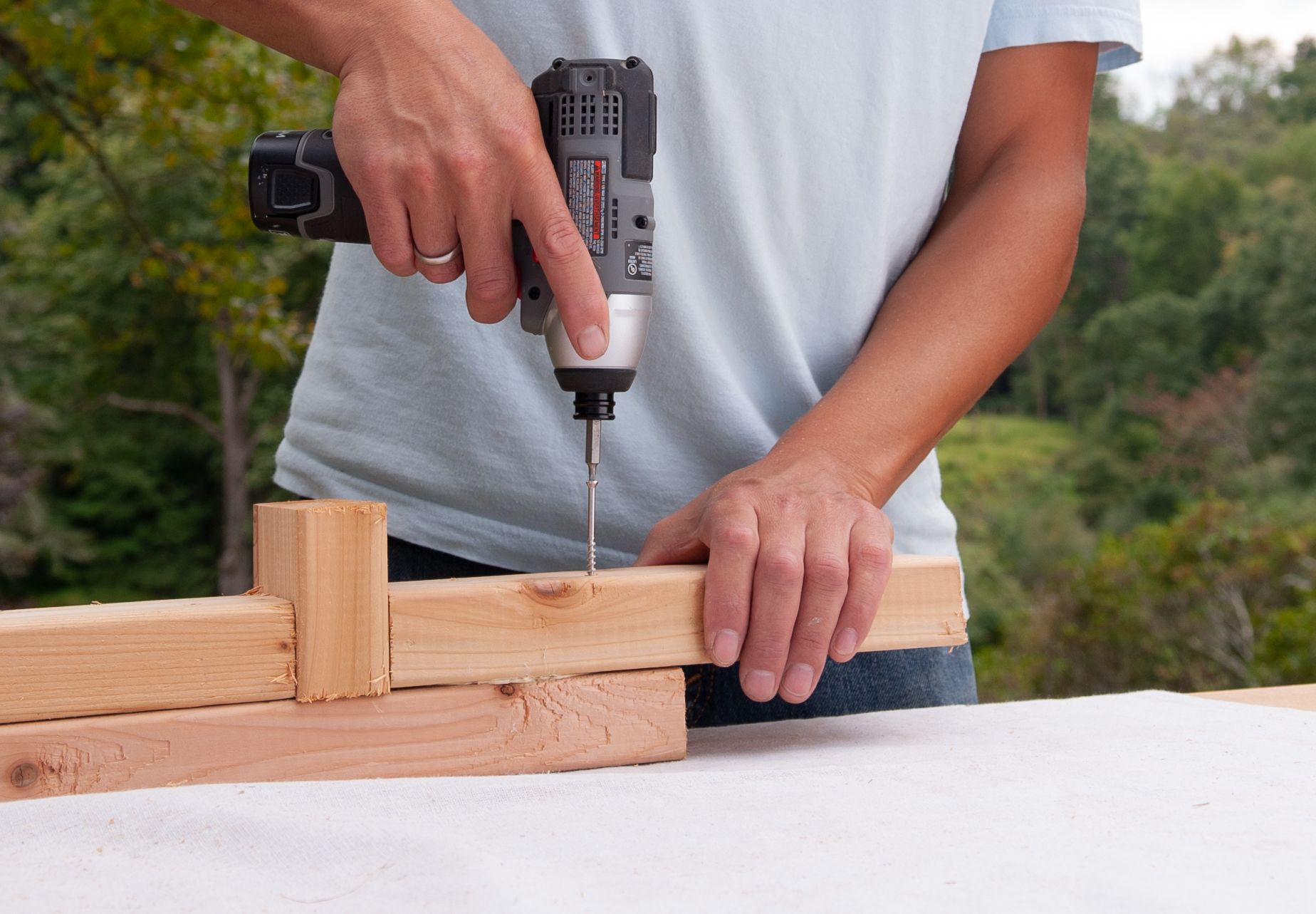
Apply construction adhesive to the backs of the support blocks. Set them in place and drive 2⅝-inch screws through them and into the longer leg piece.
Remove the spacers. Repeat for the remaining legs, laying them parallel to the first one to ensure that the gaps between support blocks are aligned.
Step 6: Install the Legs

Fit a front and back leg into the post anchors so that the sides of the legs with the support blocks face each other, as shown. Repeat for the other legs.
Step 7: Cut and Assemble the Seat Base
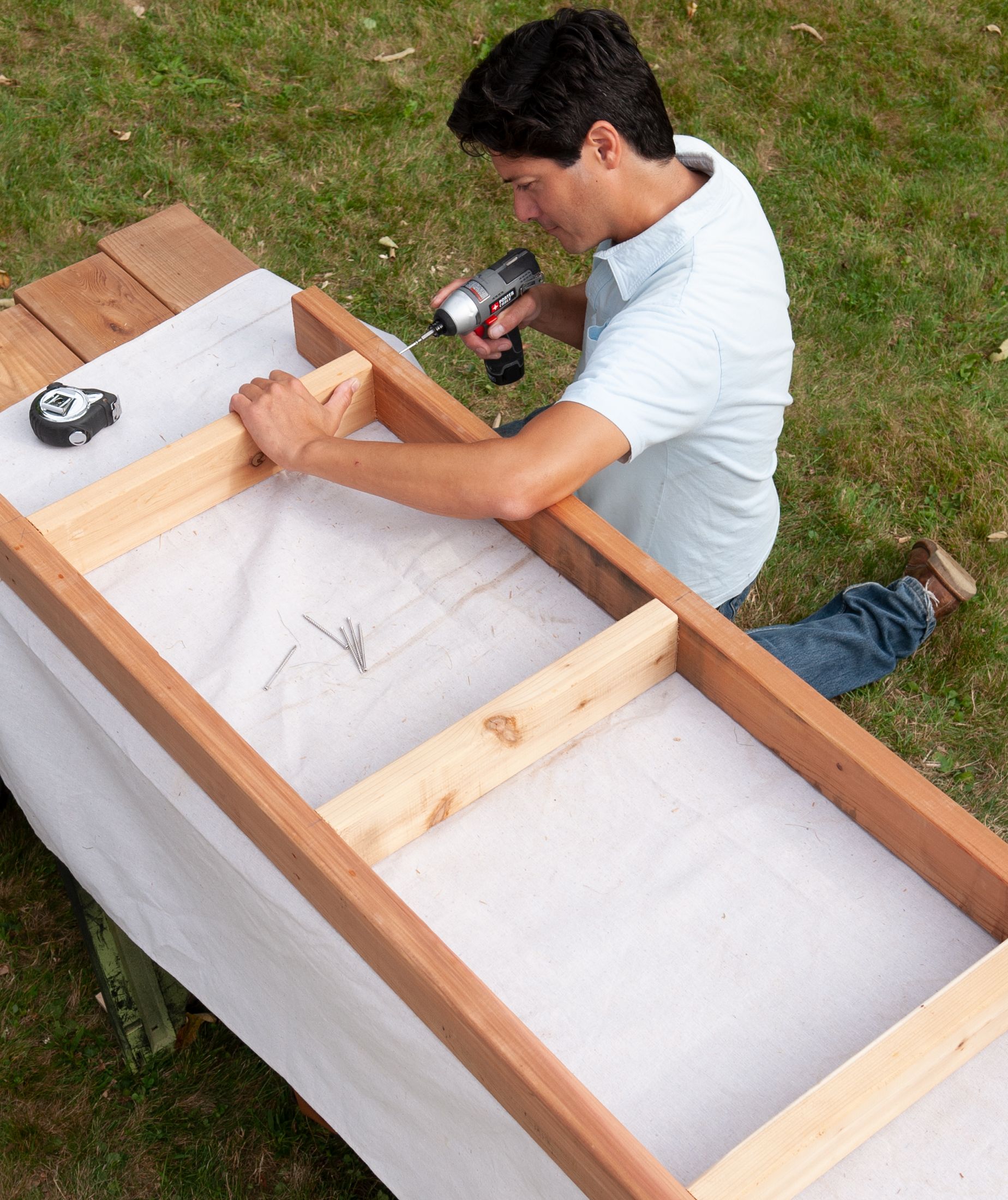
Using a miter saw, cut 2×4 pieces to size for the base, per the cut list. Sandwich the stringers between the long front and back pieces, as shown, so that the middle one is centered and the outer ones are 5 inches from the ends.
Drive 3-inch screws through the front and back pieces and into the ends of the stringers.
Step 8: Attach the Base and Lower Crosspieces
Fit the base into the 3½-inch gaps in the legs so that the ends are flush with the outer edges of the legs. Check the base for level, from front to back and side to side, and make adjustments as necessary.
Secure the base by driving 2⅝-inch screws through the front and back of the base and into the inside faces of the legs.
Cut all 2×4 crosspieces to size, and fit the lower ones into the gaps in the legs beneath the base. Secure them by toenailing 3-inch screws through the crosspieces and into the inside faces of the legs. Secure the legs to the post anchors with the supplied lag screws, adding shims if necessary.
Step 9: Cut the Pieces and Install the Side Supports
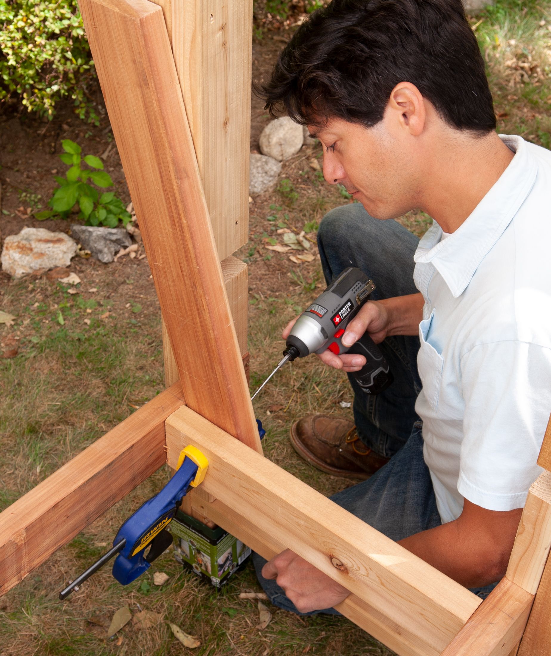
Use a miter saw to cut parallel 30-degree cuts to the ends of the backrest supports, per the cut list. Slide the side support between the leg and the seat base so that the bottom is flush with the underside of the base’s outer stringer.
Clamp it in place and drive 2⅝-inch screws through the support and into the crosspiece. Repeat on the opposite side.
Tip: If you prefer a straight backrest, square-cut the supports and reinforcement block instead of mitering them.
Step 10: Secure the Center Support
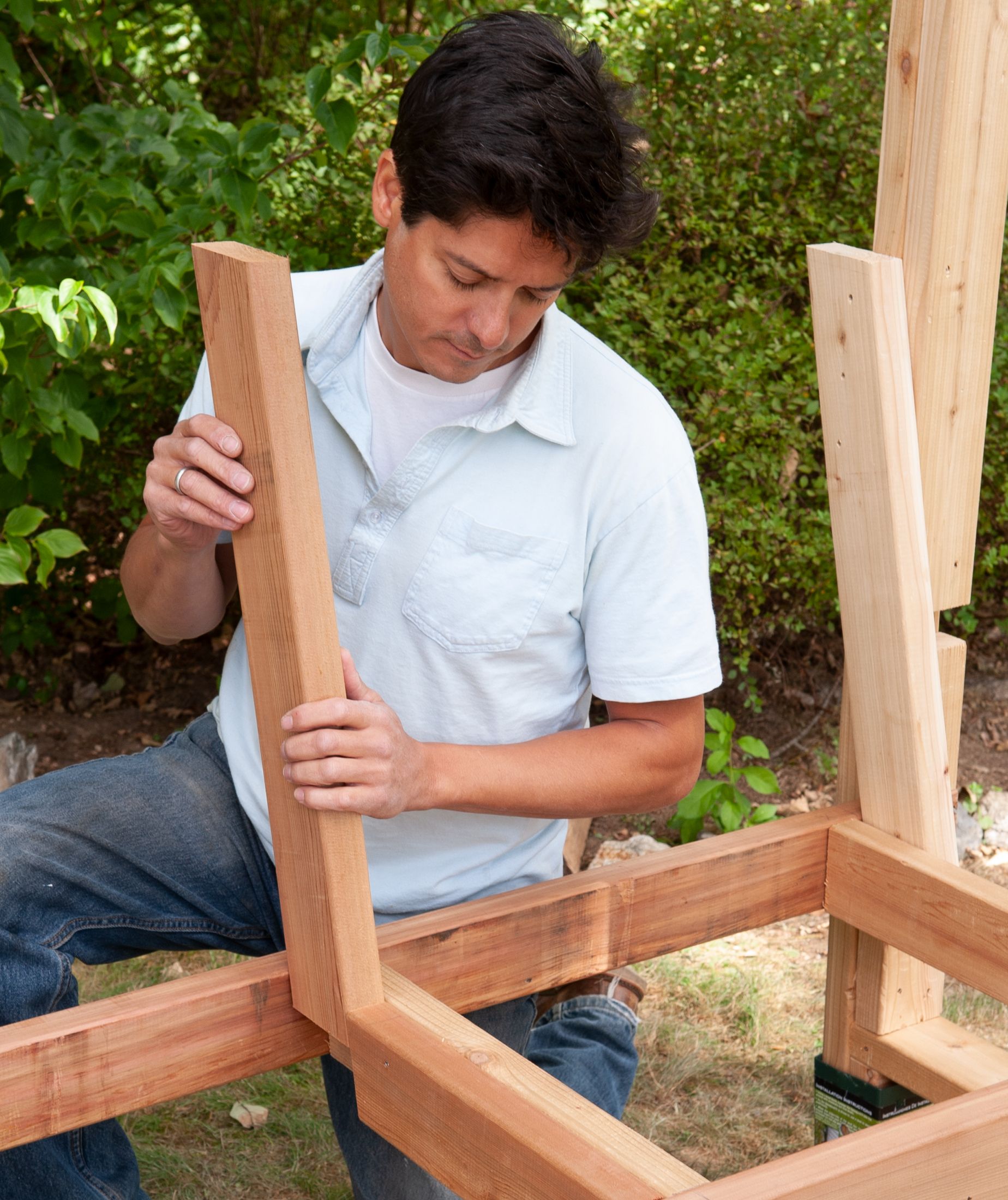
Cut a 30-degree miter off one end of a reinforcement block, per the cut list. Attach it to the seat base’s middle stringer, long edge facing upward, using 2⅝-inch screws.
Slide the backrest’s center support into the gap between the reinforcement block and the back of the seat base, as shown, until the bottom is flush with the underside of the middle stringer. Secure it by driving 2⅝-inch screws through the support and into the stringer.
Step 11: Cut the Seat Boards
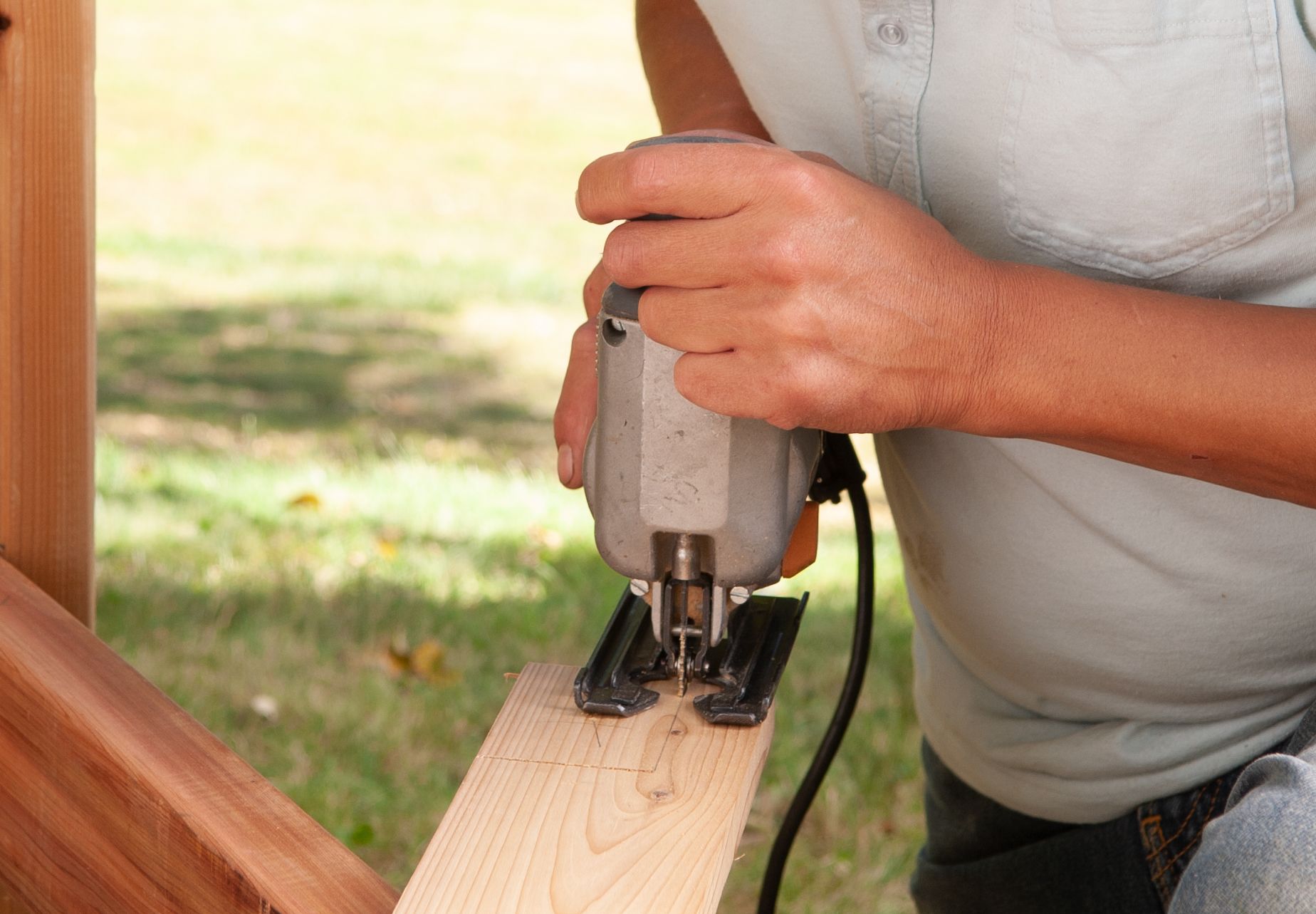
Cut 1×4 and 1×2 seat and backrest boards to size, per the cut list. The first 1×4 board at the front of the seat will extend ½ inch past the front edge of the seat’s base and must be notched at the ends to wrap around the front legs.
Mark the notch positions, 3¾ inches from each end and 2¼ inches from the board’s front edge. Use a jigsaw to cut out the notches.
Step 12: Attach the Seat Boards
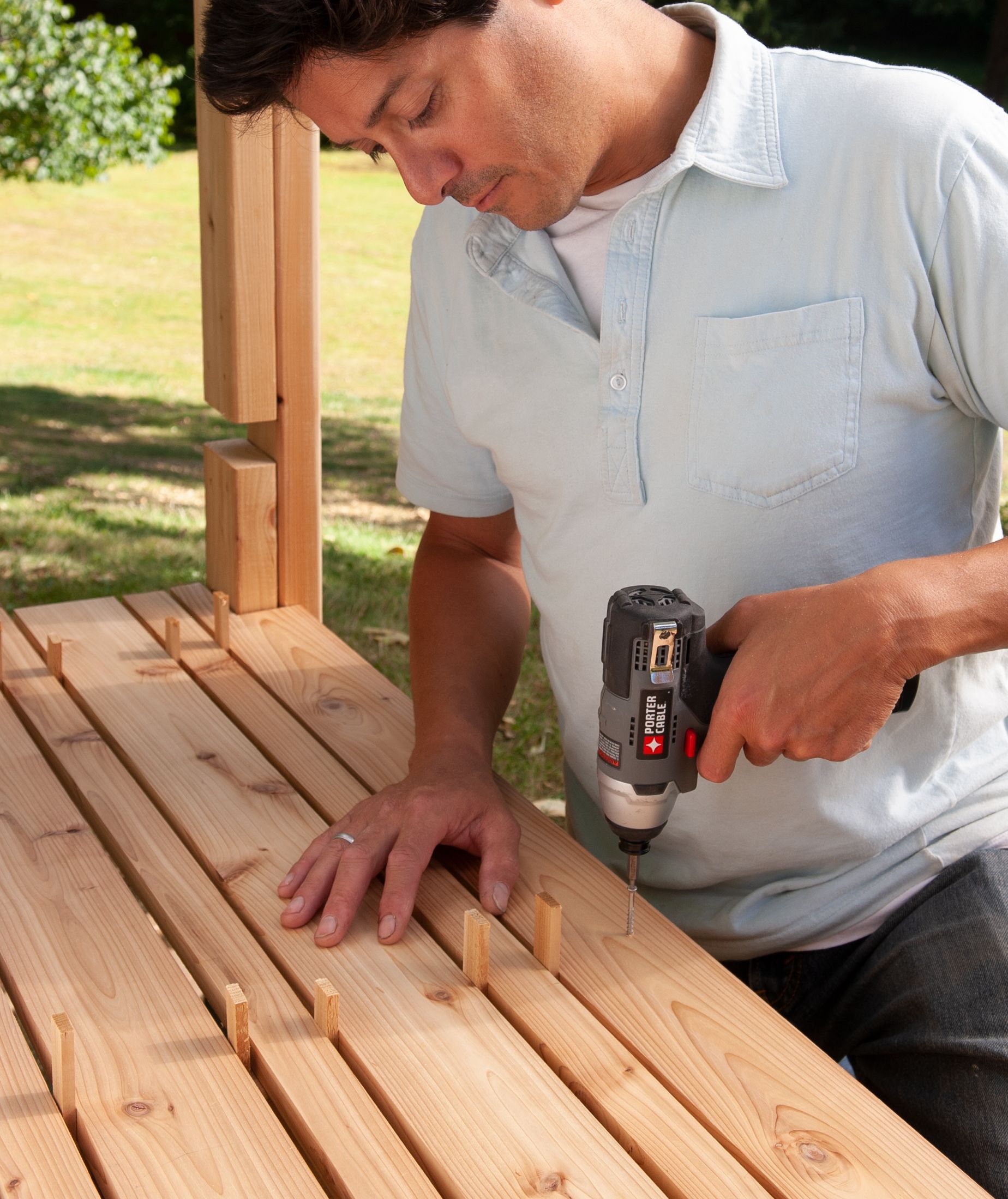
Set the notched seat board in place as shown. Lay alternating 1x2s and 1x4s behind it, using ¼-inch spacers between them.
Secure the boards by driving 1¼-inch screws through each board and into the seat base’s stringers. The screw heads will be visible, so be sure to line up the screws uniformly on each board.
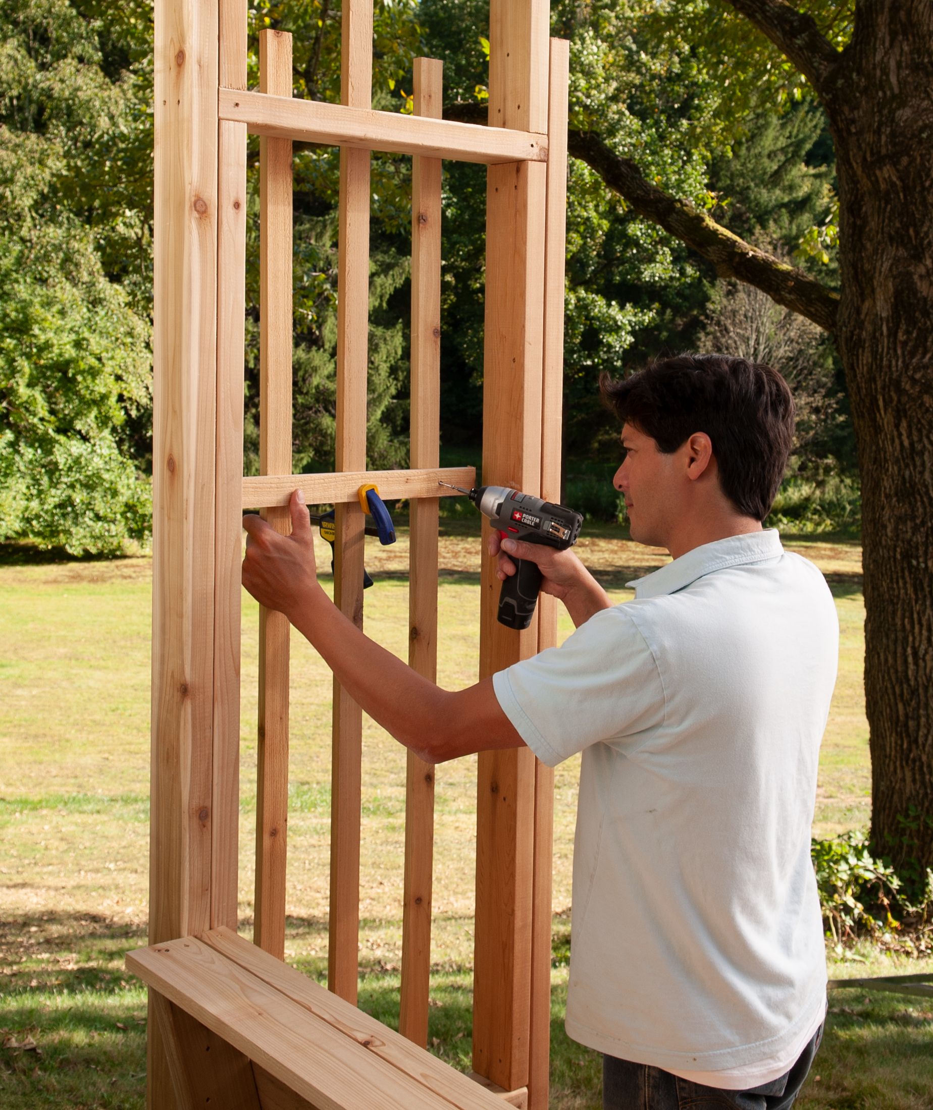
Step 13: Attach the Backrest Boards and Cap the Top
Starting at the top, place the first 1×4 board against the backrest supports, flush with their tops. Screw the board to the supports as described in Step 11. Secure alternating 1x2s and 1x4s beneath the first one, using ¼-inch spacers between them during installation.
Cut the 1×4 cap to size so that it fits between the back legs. Apply a thin bead of construction adhesive to the top edge of the first 1×4 backrest board and the tops of the backrest supports. Set the cap in place and secure it to the supports with 1¼-inch screws.
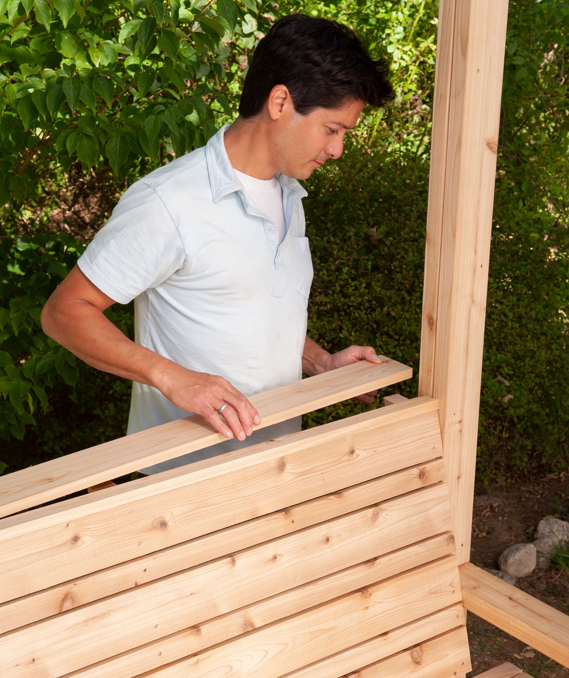
Step 14: Install the Remaining Crosspieces and Vertical Strips
Fit the upper and middle crosspieces into the gaps in the legs (the middle ones act as armrests for the bench). Secure them by toenailing 3-inch screws through the crosspieces and into the inside faces of the legs.
Cut 1×2 lattice strips to size, per the cut list. Center the longer vertical strip between the bench’s legs, and attach it to the crosspieces with 1¼-inch screws. Center the shorter strips vertically and place them equidistant from the long strip and the leg. Attach to the crosspieces with 1¼-inch screws. Repeat on the opposite side.
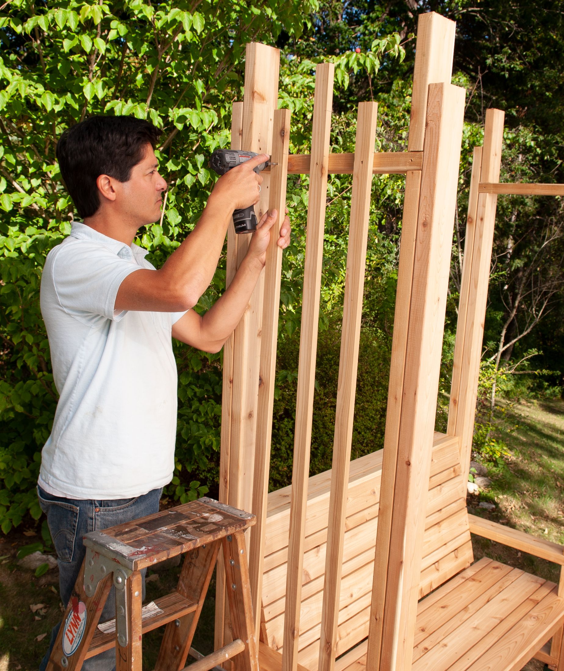
Step 15: Cut and Install Horizontal Strips
Attach the horizontal strips to the inside of the vertical strips at the desired height using 1¼-inch screws.
Step 16: Cut the Pieces and Draw the Tail Profile
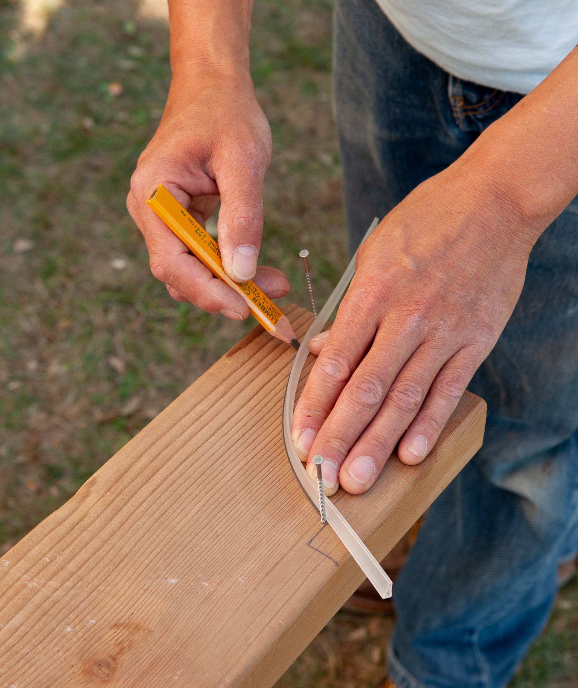
Cut 2×6 and 2×2 pieces, per the cut list. Lay a 2×6 rafter board on the flat, and use a pencil to mark the tail profile on one end.
We used a combination square to mark the straight lines; for the curve, we used a flexible plastic edge guard for a handsaw, bending it between two thin nails driven into the face of the board, as shown, to achieve a shape we liked.
Step 17: Cut the Rafter Tails
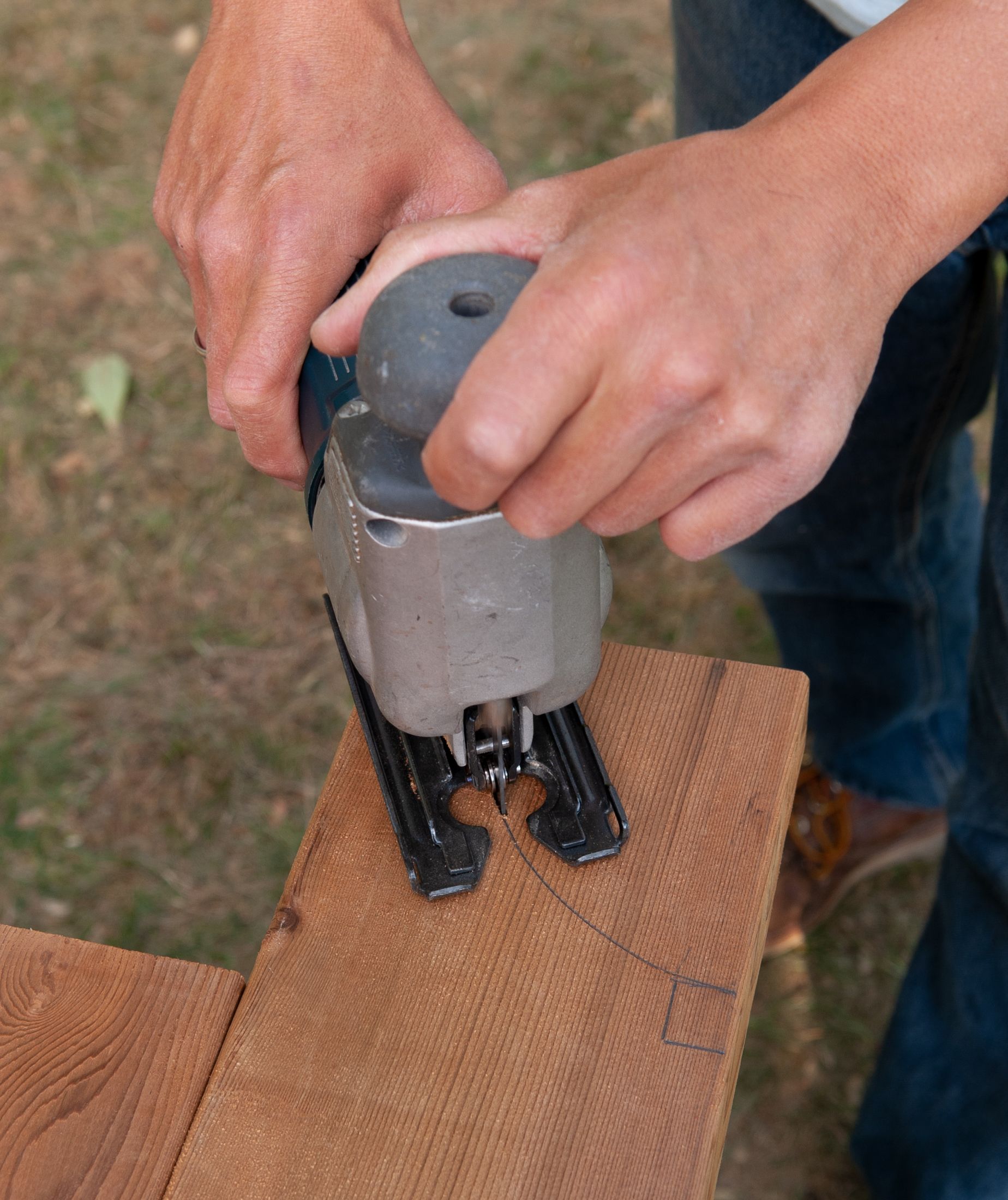
Use a jigsaw to cut the tail along the line you marked. Trace the profile onto the ends of the second rafter, and cut the tails. Then use the second rafter to trace the profile onto the opposite end of the first rafter, and cut the last tail.
Step 18: Install the Rafters
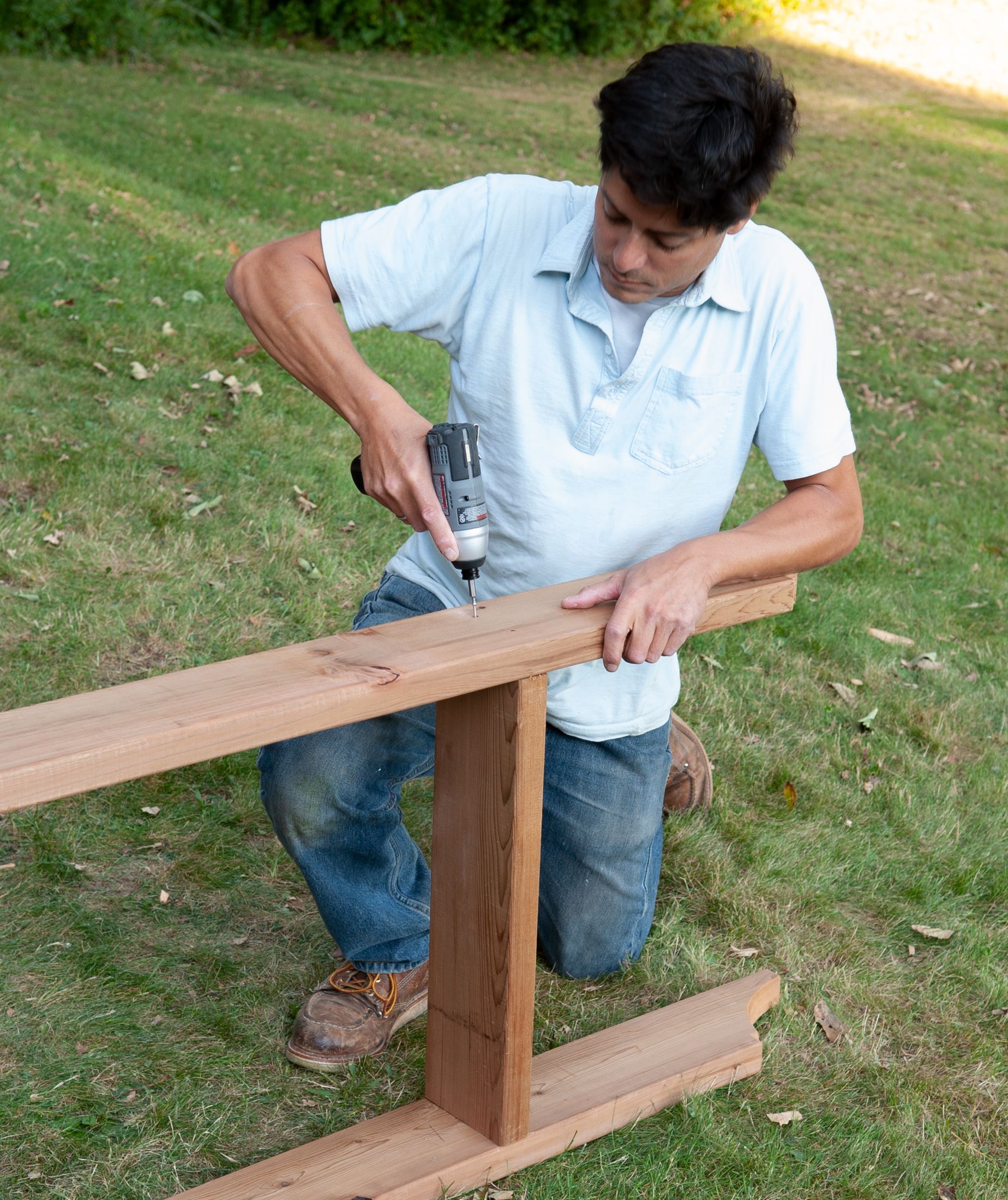
Sandwich the stringers between the rafters so that the middle one is centered and the outer ones are 15½ inches from the top tips of the rafters. Secure them by driving 3-inch screws through the rafters and into the ends of the stringers.
Set the rafter assembly in place so that the inside faces of the rafters sit against the outside faces of the top support blocks. Secure it by driving 2⅝-inch screws through the support blocks and into the inside faces of the rafters.
Step 19: Install the Purlins
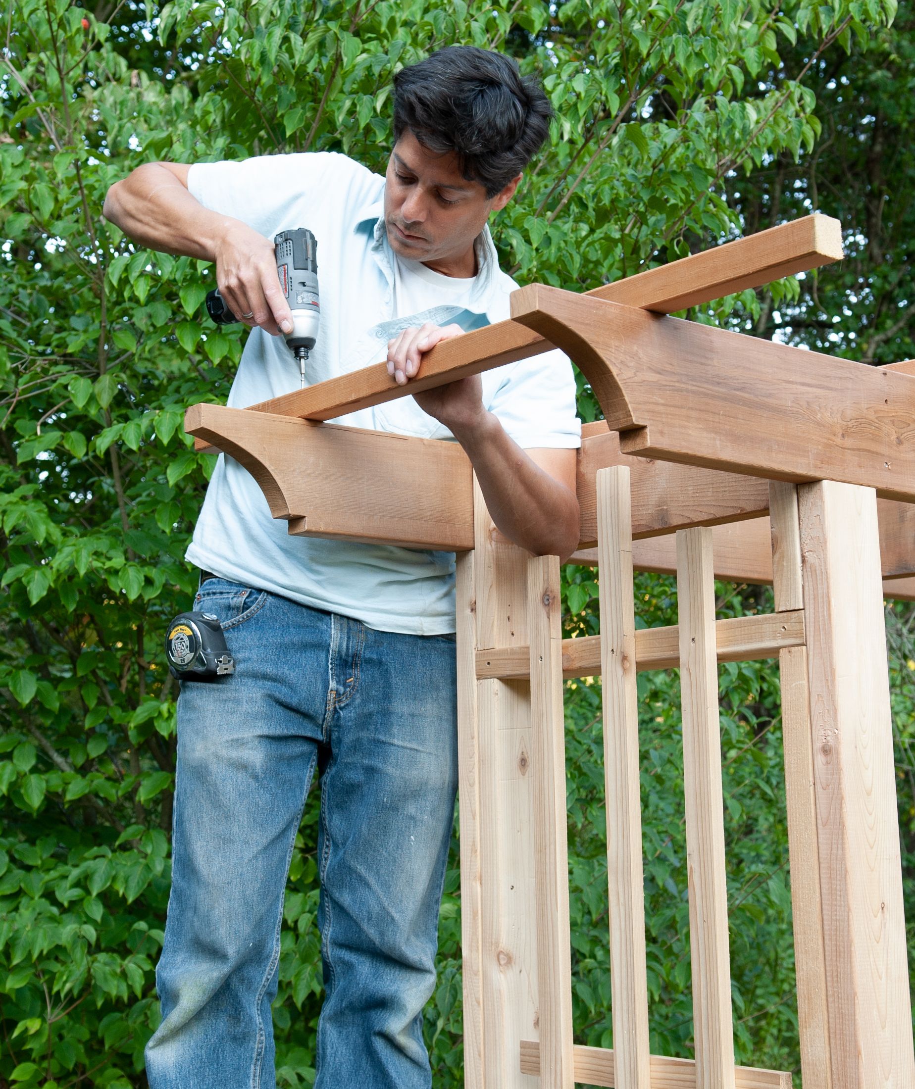
Lay evenly spaced 2×2 purlins across the top of the assembly so that the outermost ones are flush with the bottom edges of the rafter tail profiles, as shown. Secure them by driving 3-inch screws through the purlins and into the top edges of the rafters.
Finishing Touches for a Bench for Longevity
Apply a protective finish to your arbor bench for lasting durability and appearance. Choose a weather-resistant stain or sealant that complements the natural cedar. For the best results, follow the manufacturer’s instructions.
Bench Maintenance Tips
Regular maintenance will keep your arbor bench beautiful for years to come. Periodically check for any loose screws or structural issues, tightening or repairing as necessary. Clean the bench with mild soap and water to remove dirt and debris, and apply a fresh coat of sealant as needed to protect the wood from the elements.